CENELEC EN 50128: Safety-Related Software for RailwaysCENELEC EN 50128: oprogramowanie związane z bezpieczeństwem na kolei
A practical guide to EN 50128:2011: SIL 0-4, roles and independence, the software lifecycle and its documents, Annex A techniques (M/HR/R/NR), tool classes T1-T3, and how it relates to EN 50716.Praktyczny przewodnik po EN 50128:2011: SIL 0–4, role i niezależność, cykl życia oprogramowania i jego dokumenty, techniki z Załącznika A (M/HR/R/NR), klasy narzędzi T1–T3 oraz związek z EN 50716.
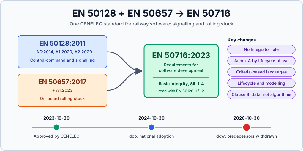
EN 50716:2023 supersedes EN 50128:2011 (with its amendments) and EN 50657:2017. The date of withdrawal of conflicting national standards (dow) is 30 October 2026.
New projects should plan for EN 50716; see EN 50128 vs EN 50716: what changed. EN 50128 remains relevant for products and safety cases that were built under it, and most of its concepts carry over.
EN 50128, “Railway applications – Communication, signalling and processing systems – Software for railway control and protection systems”, is the CENELEC standard for software in signalling and train control.
It covers interlockings, RBCs, on-board ETCS, level crossings and similar systems. The current edition is EN 50128:2011, amended by A1:2020 and A2:2020.
This article is for engineers who work with EN 50128 in a project and want the structure in one place: integrity levels, roles, lifecycle documents, techniques and tools. It summarises the standard; it does not replace it.
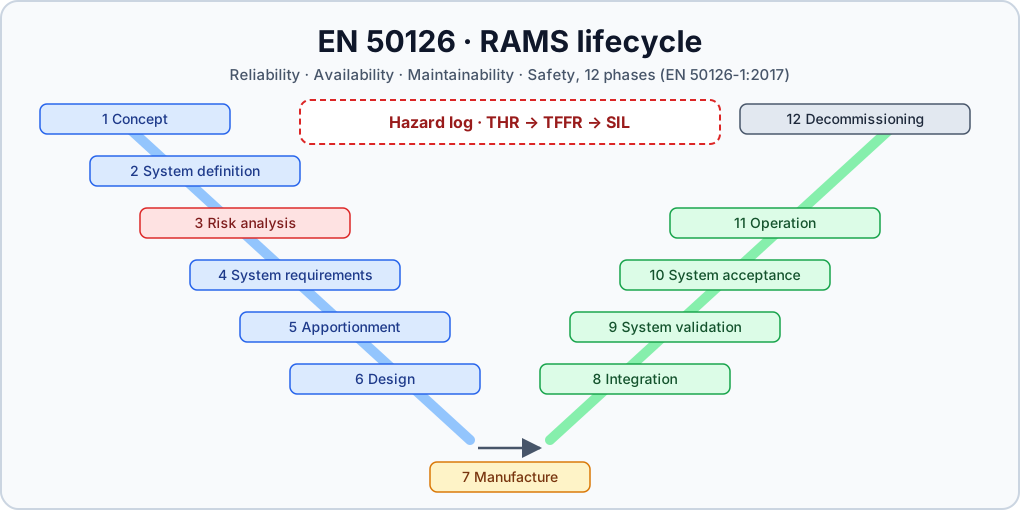
RAMS lifecycle, hazard analysis, risk acceptance, THR and SIL allocation
EN 50129
Electronic system / hardware
Safety case, safety integrity of hardware, safety-related electronic systems
EN 50128
Software
Development, verification, validation and assessment of software at a given SIL
EN 50128 applies to application software, operating systems, support tools and firmware, as far as they are used in railway control and protection systems. Rolling stock on-board software was covered separately by EN 50657:2017 until EN 50716 merged the two.
Note
The software standard receives a SIL as an input. The SIL is allocated to the function at system level (EN 50126-2, EN 50129), and then to the software that implements it. EN 50128 tells you what to do at that level, not how to choose it.
Software Safety Integrity Levels
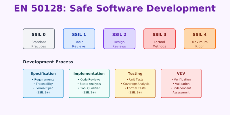
EN 50128:2011 uses software SIL 0 to 4. The 2001 edition used the term software safety integrity level (SSIL), which is why you still see “SSIL” in older documents and tool certificates.
The table shows what each level means and how Annex A groups the levels into technique columns:
SIL
Meaning in EN 50128:2011
Technique column in Annex A
SIL 0
Software that is not safety-related but is still developed under a quality process
Own column
SIL 1 / SIL 2
Safety-related software, lower integrity
Shared column: SIL 1 = SIL 2
SIL 3 / SIL 4
Safety-related software, high integrity (typical for interlocking and ATP cores)
Shared column: SIL 3 = SIL 4
The pairing matters in practice. A SIL 2 project does not get cheaper techniques than a SIL 1 project, and a SIL 3 project carries the same technique burden as a SIL 4 one.
The difference between paired levels lies elsewhere, for example in the system-level architecture and hardware safety integrity.
Note
According to commentators, the 2020 amendments already started moving away from “SIL 0” towards the Basic Integrity concept of EN 50126. EN 50716 completes that change. Check the amended text you are contractually bound to.
Roles and Independence
Clause 5 and Annex B of EN 50128 define the roles in a software project. One person may hold several roles, but some combinations are restricted depending on SIL.
Role
Main responsibility
Requirements Manager
Software requirements specification and its traceability
Designer
Software architecture, interfaces and component design
Implementer
Source code and data, according to the design
Tester
Test specifications, test execution and test reports
Integrator
Integration of components and software/hardware integration
Verifier
Verification reports for each phase: is the output consistent and complete against its input?
Validator
Whether the software as a whole meets its requirements in the intended environment; agrees or disagrees with release
Assessor
Independent judgement that the process and product meet the standard
Project Manager
Planning, resources and overall responsibility for delivery
Configuration Manager
Configuration management plan, baselines and change control
Independence grows with SIL. The table below summarises the main principles of Clause 5 as I read them.
The exact permitted combinations and reporting lines are defined in the standard’s text and its organisational figure. Use the table to orient yourself, not as a compliance argument.
Independence principle
SIL 0
SIL 1–2
SIL 3–4
Requirements Manager, Designer and Implementer may be one person
Yes
Yes
Yes
Integrator and Tester may be one person
Yes
Yes
Yes
Verifier independent of Requirements Manager, Designer and Implementer
Reduced; see text
Required
Required
Validator independent of Requirements Manager, Designer and Implementer
Reduced; see text
Required
Required
Validator may report to the Project Manager
See text
Generally permitted; see text
Not permitted
Verifier’s reporting line
See text
Less restrictive; see text
Project Manager or Validator, depending on the organisational option
Assessor independent of the project
Reduced; see text
Required
Required
At SIL 3 and SIL 4 the key point is the Validator: whatever organisational option you choose, the Validator must not report to the Project Manager.
Independence is about people and reporting lines
Independence is not satisfied by a different job title. Check who reports to whom, who can influence release, and whether commercial or schedule pressure can reach the Verifier, Validator or Assessor.
The Assessor must be independent of the project and is normally accepted by the customer or the safety authority.
Lifecycle and Documents
EN 50128 does not mandate a waterfall, but it expects every phase to produce defined documents, each verified before the next phase relies on it.
The V-shaped pairing is the core idea: every specification on the left has a test specification and a report on the right.
  Requirements spec ----------------------> Overall software test
     Architecture & design spec ------> SW/HW integration test
        Component design spec ------> Component test
              Component implementation (code)
The table below lists the main phases with their clause and typical documents. Document names follow the standard; your project templates may merge some of them.
Clause 6 (software assurance) runs across all phases:
testing (6.1),
verification (6.2),
validation (6.3),
assessment (6.4),
quality assurance (6.5),
modification and change control (6.6),
support tools and languages (6.7).
Configuration management applies at every SIL, including SIL 0.
Traceability is the backbone
In practice, many assessment findings come down to traceability gaps: a requirement with no test, a test with no requirement, or a design element that traces to nothing. Set up bidirectional traceability between requirements, design, code and tests from day one; retrofitting it before assessment is expensive.
Verification vs validation
Verification answers “did we build it right?” for each phase: is the phase output complete, consistent and correct with respect to its input, and was the plan followed? It produces a verification report per phase.
Validation answers “did we build the right thing?” for the software as a whole: does it meet its requirements, including safety requirements, in its intended environment? The Validator also agrees or disagrees with release.
Assessment sits above both: an independent judgement that the process and the product conform to the standard.
Techniques and Measures (Annex A)
Annex A is where SIL becomes concrete. For each phase, a table lists techniques and measures with a rating per SIL column:
Rating
Meaning
M
Mandatory: the technique must be used
HR
Highly recommended: if not used, the rationale must be documented and justified
R
Recommended: a lower-priority option
–
No recommendation for or against
NR
Not recommended: if used, the rationale must be documented and justified
Many tables also allow approved combinations. A note under the table states which groups of techniques together satisfy the requirement for a SIL.
Choose a combination deliberately and record it in the SQAP or a technique selection matrix.
The table below shows the general direction of travel for common technique groups. I wrote it from my working knowledge of the 2011 tables: it is an orientation, not a substitute for the published tables.
Technique group
SIL 0
SIL 1–2
SIL 3–4
Structured methodology, modular approach
Expected
Expected, often M or HR
Expected, often M or HR
Formal methods (specification, design)
–
R
HR
Modelling
– or R
R
HR
Design and coding standards
HR
HR
Strengthened, often M
Strongly typed programming language
R
HR
HR
Static analysis
–
HR
HR
Functional / black-box testing
HR
HR
Strengthened, often M
Test coverage for code
R
HR
HR, with stronger coverage criteria
Traceability
R
HR
Strengthened, often M
Artificial intelligence fault correction
–
NR
NR
Do not copy ratings from blog posts
Ratings, approved combinations and the exact names of techniques differ between the 2011 text, the 2020 amendments and EN 50716. Build your compliance matrix from the edition named in your contract, and justify every HR technique you do not use.
Design principles behind the tables
Many Annex A entries express a handful of design principles you can apply at any SIL:
Separation and partitioning: isolate higher-SIL software from lower-SIL or non-safety software, with clear interfaces.
Defensive programming: validate all external inputs, check ranges and plausibility, handle timeouts.
Fail-safe behaviour: explicit error paths, safe defaults and no silent failures.
Limited language features: no dynamic memory after initialisation, bounded loops, no recursion where a subset forbids it.
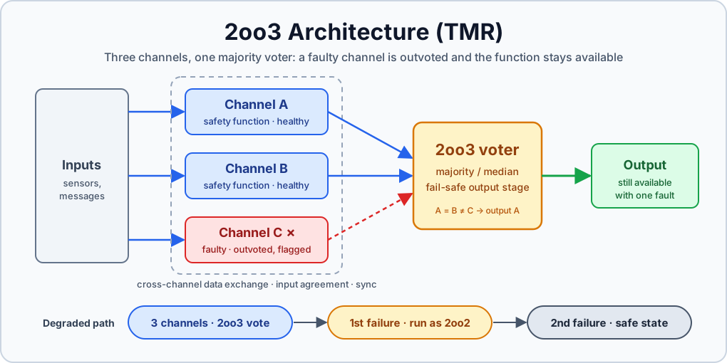
Redundancy and voting (for example 2oo2 architectures) are mostly a system and hardware topic under EN 50129. The software must still be designed for them, for example by comparing channel outputs or using diverse implementations.
Support Tools (T1, T2, T3)
Clause 6.7 classifies every tool used in software development:
Class
Definition (paraphrased)
Examples
Evidence required
T1
Generates no outputs that can directly or indirectly contribute to the executable code (including data)
Text editor, requirements tool without code generation
Little beyond selection as part of the process
T2
Supports test or verification; errors can fail to reveal defects but cannot directly create errors in the executable
Static analyser, test coverage tool, test harness
Justified selection, specification or manual, evidence the tool does what it claims
T3
Generates outputs that can directly or indirectly contribute to the executable code (including data)
Compiler, linker, code generator, data preparation tool
As T2, plus evidence the output conforms to its specification or that tool failures are detected
For T3 tools, that evidence typically comes from proven use, tool validation or diverse checks of the output.
The tool version is part of the configuration. A compiler upgrade is a change that needs impact analysis, even if no source line changes.
Tip
A T3 qualification argument is often cheaper when the tool’s failures are detected downstream, for example by testing the object code or by diverse checks on generated data, than by trying to prove the tool correct.
Common Mistakes
Treating SIL as a software decision. The software SIL comes from the system safety analysis. If no one can point to the allocation in the hazard log or system safety requirements, stop and ask.
Ignoring the SIL pairing. A SIL 2 project carries the same technique burden as SIL 1, and SIL 3 the same as SIL 4.
Weak independence. A Verifier who sits in the Implementer’s team, or a Validator who reports to the Project Manager at SIL 3/4, will not survive assessment.
Missing rationales. Not using an HR technique is allowed, but only with a documented justification.
Uncontrolled tools. Tools without class, version and justification in the configuration records.
Ignoring EN 50716. With the dow on 30 October 2026, agree with your assessor which edition each project follows.
EN 50128:2011, EN 50128:2011/A1:2020, EN 50128:2011/A2:2020
EN 50716:2023, EN 50126-1:2017, EN 50126-2:2017, EN 50129:2018
EN 50128 została zastąpiona
EN 50716:2023 zastępuje EN 50128:2011 (wraz ze zmianami) oraz EN 50657:2017. Data wycofania sprzecznych norm krajowych (dow) to 30 października 2026 r.
Nowe projekty powinny od razu zakładać EN 50716 – zob. EN 50128 a EN 50716: co się zmieniło. EN 50128 pozostaje jednak ważna dla wyrobów i dowodów bezpieczeństwa (safety case) przygotowanych według niej, a większość jej pojęć przechodzi do nowej normy.
EN 50128, „Railway applications – Communication, signalling and processing systems – Software for railway control and protection systems”, to norma CENELEC dotycząca oprogramowania urządzeń sterowania ruchem kolejowym (srk) i systemów kontroli jazdy pociągu.
Obejmuje m.in. urządzenia zależnościowe, centra RBC, pokładowe ETCS i systemy przejazdowe. Obowiązujące wydanie to EN 50128:2011 ze zmianami A1:2020 i A2:2020.
Artykuł jest przeznaczony dla inżynierów, którzy pracują z EN 50128 w projekcie i chcą mieć jej strukturę w jednym miejscu: poziomy nienaruszalności, role, dokumenty cyklu życia, techniki i narzędzia. To streszczenie normy, a nie jej zamiennik.
Cykl życia RAMS, analiza zagrożeń, akceptacja ryzyka, przydział THR i SIL
EN 50129
System elektroniczny / sprzęt
Dowód bezpieczeństwa, nienaruszalność bezpieczeństwa sprzętu, elektroniczne systemy związane z bezpieczeństwem
EN 50128
Oprogramowanie
Wytwarzanie, weryfikacja, walidacja i ocena oprogramowania na danym SIL
EN 50128 dotyczy oprogramowania aplikacyjnego, systemów operacyjnych, narzędzi wspomagających i firmware’u, o ile są używane w kolejowych systemach sterowania i zabezpieczenia. Oprogramowanie pokładowe taboru podlegało osobnej normie, EN 50657:2017, dopóki EN 50716 nie połączyła obu zakresów.
Note
SIL jest dla normy dotyczącej oprogramowania daną wejściową. Przypisuje się go funkcji na poziomie systemu (EN 50126-2, EN 50129), a dopiero potem oprogramowaniu, które tę funkcję realizuje. EN 50128 mówi, co robić na danym poziomie, a nie jak go wybrać.
Poziomy nienaruszalności oprogramowania
EN 50128:2011 stosuje poziomy nienaruszalności bezpieczeństwa oprogramowania SIL 0–4. Wydanie z 2001 r. używało terminu software safety integrity level (SSIL), dlatego skrót „SSIL” wciąż można spotkać w starszych dokumentach i certyfikatach narzędzi.
Tabela pokazuje, co oznacza każdy poziom i jak Załącznik A łączy poziomy w kolumny technik:
SIL
Znaczenie w EN 50128:2011
Kolumna technik w Załączniku A
SIL 0
Oprogramowanie niezwiązane z bezpieczeństwem, ale wytwarzane w ramach systemu jakości
Osobna kolumna
SIL 1 / SIL 2
Oprogramowanie związane z bezpieczeństwem, niższy poziom nienaruszalności
Wspólna kolumna: SIL 1 = SIL 2
SIL 3 / SIL 4
Oprogramowanie związane z bezpieczeństwem, wysoki poziom nienaruszalności (typowo rdzeń urządzeń zależnościowych i ATP)
Wspólna kolumna: SIL 3 = SIL 4
To łączenie poziomów w pary ma praktyczne skutki. Projekt SIL 2 nie może stosować tańszych technik niż projekt SIL 1, a projekt SIL 3 wymaga tych samych technik co SIL 4.
Różnice między poziomami w parze leżą gdzie indziej, np. w architekturze systemu i nienaruszalności bezpieczeństwa sprzętu.
Note
Według komentatorów już zmiany z 2020 r. zaczęły odchodzić od „SIL 0” na rzecz pojęcia Basic Integrity z EN 50126. EN 50716 doprowadziła tę zmianę do końca. Sprawdź tekst ze zmianami, który wiąże Cię kontraktowo.
Role i niezależność
Rozdział 5 i Załącznik B normy EN 50128 definiują role w projekcie oprogramowania. Jedna osoba może pełnić kilka ról, ale niektóre połączenia są – zależnie od SIL – niedozwolone.
Rola
Główna odpowiedzialność
Kierownik wymagań (Requirements Manager)
Specyfikacja wymagań oprogramowania i śledzenie powiązań
Projektant (Designer)
Architektura oprogramowania, interfejsy i projekt komponentów
Implementator (Implementer)
Kod źródłowy i dane zgodne z projektem
Tester
Specyfikacje testów, wykonanie testów i raporty z testów
Integrator
Integracja komponentów oraz integracja oprogramowania ze sprzętem
Weryfikator (Verifier)
Raporty z weryfikacji każdej fazy: czy wynik jest spójny i kompletny względem danych wejściowych?
Walidator (Validator)
Ocena, czy oprogramowanie jako całość spełnia wymagania w docelowym środowisku; zgoda lub sprzeciw wobec wydania
Asesor (Assessor)
Niezależna ocena, czy proces i produkt spełniają wymagania normy
Kierownik projektu (Project Manager)
Planowanie, zasoby i ogólna odpowiedzialność za dostawę
Kierownik konfiguracji (Configuration Manager)
Plan zarządzania konfiguracją, konfiguracje bazowe (baseline) i kontrola zmian
Wymagania niezależności rosną wraz z SIL. Poniższa tabela streszcza główne zasady z rozdziału 5 w moim odczytaniu.
Dokładne dopuszczalne połączenia ról i linie podległości określają tekst normy i jej rysunek struktury organizacyjnej. Traktuj tabelę jako mapę, a nie argument w wykazaniu zgodności.
Zasada niezależności
SIL 0
SIL 1–2
SIL 3–4
Kierownik wymagań, projektant i implementator mogą być jedną osobą
Tak
Tak
Tak
Integrator i tester mogą być jedną osobą
Tak
Tak
Tak
Weryfikator niezależny od kierownika wymagań, projektanta i implementatora
Złagodzone; zob. tekst
Wymagane
Wymagane
Walidator niezależny od kierownika wymagań, projektanta i implementatora
Złagodzone; zob. tekst
Wymagane
Wymagane
Walidator może podlegać kierownikowi projektu
Zob. tekst
Na ogół dopuszczalne; zob. tekst
Niedopuszczalne
Komu podlega weryfikator
Zob. tekst
Mniej restrykcyjnie; zob. tekst
Kierownikowi projektu lub walidatorowi, zależnie od wariantu organizacyjnego
Asesor niezależny od projektu
Złagodzone; zob. tekst
Wymagane
Wymagane
Przy SIL 3 i SIL 4 kluczowy jest walidator: niezależnie od wybranego wariantu organizacyjnego nie może podlegać kierownikowi projektu.
Niezależność to kwestia ludzi i podległości
Inna nazwa stanowiska nie zapewnia niezależności. Sprawdź, kto komu podlega, kto może wpłynąć na decyzję o wydaniu i czy presja handlowa lub terminowa może dosięgnąć weryfikatora, walidatora albo asesora.
Asesor musi być niezależny od projektu i zwykle jest akceptowany przez klienta lub organ bezpieczeństwa.
Cykl życia i dokumenty
EN 50128 nie narzuca modelu kaskadowego, ale wymaga, by każda faza dała określone dokumenty, zweryfikowane, zanim następna faza zacznie z nich korzystać.
Podstawą jest układ w kształcie litery V: każdej specyfikacji po lewej stronie odpowiada specyfikacja testów i raport po prawej.
  Specyfikacja wymagań ---------------> Testy całego oprogramowania
     Specyfikacja architektury --------> Testy integracji SW/HW
        Projekt komponentów --------> Testy komponentów
              Implementacja komponentów (kod)
Tabela zestawia główne fazy z rozdziałami normy i typowymi dokumentami. Nazwy dokumentów podaję w brzmieniu oryginalnym; szablony w projekcie mogą łączyć niektóre z nich.
Rozdział 6 (zapewnienie oprogramowania) obejmuje wszystkie fazy:
testowanie (6.1),
weryfikację (6.2),
walidację (6.3),
ocenę (6.4),
zapewnienie jakości (6.5),
modyfikacje i kontrolę zmian (6.6),
narzędzia wspomagające i języki (6.7).
Zarządzanie konfiguracją obowiązuje na każdym poziomie, także przy SIL 0.
Śledzenie powiązań to kręgosłup projektu
W praktyce wiele uwag asesora sprowadza się do luk w śledzeniu powiązań (traceability): wymaganie bez testu, test bez wymagania albo element projektu, którego nie da się powiązać z niczym. Dwukierunkowe powiązania między wymaganiami, projektem, kodem i testami warto zbudować od pierwszego dnia – odtwarzanie ich tuż przed oceną jest drogie.
Weryfikacja a walidacja
Weryfikacja odpowiada na pytanie „czy budujemy produkt dobrze?” w każdej fazie: czy wynik fazy jest kompletny, spójny i poprawny względem danych wejściowych i czy postępowano zgodnie z planem? Jej efektem jest raport z weryfikacji dla każdej fazy.
Walidacja odpowiada na pytanie „czy budujemy właściwy produkt?” dla oprogramowania jako całości: czy spełnia wymagania, w tym wymagania bezpieczeństwa, w docelowym środowisku? Walidator wyraża też zgodę lub sprzeciw wobec wydania.
Ocena (assessment) jest nadrzędna wobec obu: to niezależny osąd, czy proces i produkt są zgodne z normą.
Techniki i środki (Załącznik A)
To w Załączniku A poziom SIL nabiera konkretnej treści. Dla każdej fazy tabela wymienia techniki i środki wraz z oceną dla każdej kolumny SIL:
Ocena
Znaczenie
M
Obowiązkowe (mandatory): technikę trzeba zastosować
HR
Wysoce zalecane (highly recommended): rezygnację trzeba udokumentować i uzasadnić
R
Zalecane (recommended): opcja o niższym priorytecie
–
Brak zalecenia za ani przeciw
NR
Niezalecane (not recommended): zastosowanie trzeba udokumentować i uzasadnić
Wiele tabel dopuszcza też zatwierdzone kombinacje. Uwaga pod tabelą określa, które zestawy technik łącznie spełniają wymaganie dla danego SIL.
Kombinację warto wybrać świadomie i zapisać w SQAP albo w macierzy doboru technik.
Poniższa tabela pokazuje ogólny kierunek zmian dla typowych grup technik. Przygotowałem ją na podstawie praktycznej znajomości tabel z 2011 r.: to orientacja, a nie zamiennik opublikowanych tabel.
Grupa technik
SIL 0
SIL 1–2
SIL 3–4
Metodyka strukturalna, podejście modułowe
Oczekiwane
Oczekiwane, często M lub HR
Oczekiwane, często M lub HR
Metody formalne (specyfikacja, projekt)
–
R
HR
Modelowanie
– lub R
R
HR
Standardy projektowania i kodowania
HR
HR
Zaostrzone, często M
Język programowania z silną kontrolą typów
R
HR
HR
Analiza statyczna
–
HR
HR
Testy funkcjonalne (czarnoskrzynkowe)
HR
HR
Zaostrzone, często M
Pokrycie kodu testami
R
HR
HR, z ostrzejszymi kryteriami pokrycia
Śledzenie powiązań
R
HR
Zaostrzone, często M
Korekcja błędów z użyciem sztucznej inteligencji
–
NR
NR
Nie kopiuj ocen z blogów
Oceny, zatwierdzone kombinacje i dokładne nazwy technik różnią się między tekstem z 2011 r., zmianami z 2020 r. i EN 50716. Macierz zgodności buduj na podstawie wydania wskazanego w kontrakcie i uzasadnij każdą niezastosowaną technikę HR.
Zasady projektowe stojące za tabelami
Wiele pozycji Załącznika A sprowadza się do kilku zasad projektowych, które można stosować na każdym poziomie SIL:
Separacja i partycjonowanie: oddziel oprogramowanie o wyższym SIL od oprogramowania o niższym SIL lub niezwiązanego z bezpieczeństwem i zdefiniuj jasne interfejsy.
Programowanie defensywne: sprawdzaj wszystkie dane zewnętrzne, kontroluj zakresy i wiarygodność, obsługuj przekroczenia czasu.
Zachowanie bezpieczne przy uszkodzeniu (fail-safe): jawne ścieżki obsługi błędów, bezpieczne wartości domyślne i żadnych „cichych” awarii.
Ograniczony zestaw konstrukcji języka: brak dynamicznej alokacji pamięci po inicjalizacji, ograniczone pętle, brak rekurencji tam, gdzie zabrania jej przyjęty podzbiór języka.
Redundancja i głosowanie (np. architektury 2oo2) to głównie temat systemowy i sprzętowy, regulowany przez EN 50129. Oprogramowanie trzeba jednak do nich przygotować, np. przez porównywanie wyników kanałów albo zróżnicowane implementacje.
Narzędzia wspomagające (T1, T2, T3)
Punkt 6.7 klasyfikuje każde narzędzie używane przy wytwarzaniu oprogramowania:
Klasa
Definicja (w uproszczeniu)
Przykłady
Wymagane dowody
T1
Nie generuje wyników, które mogą bezpośrednio lub pośrednio trafić do kodu wykonywalnego (łącznie z danymi)
Edytor tekstu, narzędzie do wymagań bez generowania kodu
Niewiele ponad uzasadniony wybór w ramach procesu
T2
Wspiera testowanie lub weryfikację; błąd narzędzia może przeoczyć defekt, ale nie może bezpośrednio wprowadzić błędu do kodu wykonywalnego
Analizator statyczny, narzędzie do pomiaru pokrycia, środowisko testowe
Uzasadniony wybór, specyfikacja lub instrukcja, dowód, że narzędzie robi to, co deklaruje
T3
Generuje wyniki, które mogą bezpośrednio lub pośrednio trafić do kodu wykonywalnego (łącznie z danymi)
Kompilator, linker, generator kodu, narzędzie do przygotowania danych
Jak dla T2, a do tego dowód zgodności wyniku ze specyfikacją albo wykrywania błędów narzędzia
W przypadku narzędzi T3 taki dowód pochodzi zwykle z udokumentowanej historii stosowania (proven in use), walidacji narzędzia albo zróżnicowanej kontroli jego wyników.
Wersja narzędzia jest częścią konfiguracji. Aktualizacja kompilatora to zmiana wymagająca analizy wpływu, nawet jeśli w kodzie źródłowym nie zmieniła się ani jedna linia.
Tip
Uzasadnienie kwalifikacji narzędzia T3 jest często tańsze, gdy błędy narzędzia wykrywa się na dalszych etapach – np. przez testowanie kodu wynikowego albo zróżnicowaną kontrolę wygenerowanych danych – niż gdy próbuje się udowodnić poprawność samego narzędzia.
Typowe błędy
Traktowanie SIL jako decyzji zespołu oprogramowania. SIL oprogramowania wynika z systemowej analizy bezpieczeństwa. Jeśli nikt nie potrafi wskazać przydziału w rejestrze zagrożeń lub w systemowych wymaganiach bezpieczeństwa, zatrzymaj się i zapytaj.
Pomijanie łączenia poziomów w pary. Projekt SIL 2 wymaga tych samych technik co SIL 1, a SIL 3 – tych samych co SIL 4.
Pozorna niezależność. Weryfikator pracujący w zespole implementatora albo walidator podległy kierownikowi projektu przy SIL 3/4 nie przejdą oceny.
Brak uzasadnień. Rezygnacja z techniki HR jest dopuszczalna, ale tylko z udokumentowanym uzasadnieniem.
Narzędzia poza kontrolą. Narzędzia bez określonej klasy, wersji i uzasadnienia w zapisach zarządzania konfiguracją.
Pomijanie EN 50716. Ponieważ dow przypada na 30 października 2026 r., uzgodnij z asesorem, według którego wydania prowadzony jest każdy projekt.
EN 50128:2011 and EN 50657:2017 vs their successor EN 50716:2023: dates, scope, clause-by-clause changes, Basic Integrity, roles, tools, languages, and a transition checklist before the 2026 dow.EN 50128:2011 i EN 50657:2017 a ich następczyni EN 50716:2023: daty, zakres, zmiany rozdział po rozdziale, Basic Integrity, role, narzędzia, języki i lista kontrolna przed dow w 2026 r.
A practical guide to EN 50126-1/-2:2017: the 12-phase RAMS lifecycle, hazard log, CSM-RA-aligned risk acceptance, roles, independent safety assessment and THR/TFFR/SIL apportionment.Praktyczny przewodnik po EN 50126-1/-2:2017: 12-fazowy cykl życia systemu, rejestr zagrożeń, zasady akceptacji ryzyka zgodne z CSM-RA, role, niezależna ocena bezpieczeństwa oraz podział THR/TFFR/SIL.
How 2oo3 (TMR) voting works, how to design the voter, what happens after the first channel failure, and how 2oo3 compares with 2oo2 and 1oo2 using IEC 61508-6 PFD/PFH formulas.Jak działa głosowanie 2oo3 (TMR), jak zaprojektować układ głosujący, co się dzieje po pierwszym uszkodzeniu kanału i jak 2oo3 wypada na tle 2oo2 i 1oo2 według wzorów PFD/PFH z IEC 61508-6.